The Invisible Current Eating Your Aluminum Components
Few mechanical failures frustrate fleet maintenance supervisors and design engineers quite like recurring radiator pinholes or eroded water pump impellers. When an aluminum heat exchanger perforates within 6,000 miles of installation, the natural impulse is to blame the component supplier for thin brazing or porous casting. Yet, in a staggering number of premature cooling system failures, the root culprit is not metallurgical defect—it is electrical current flowing where it does not belong. Understanding what causes coolant electrolysis is critical for diagnosing persistent cooling failures before they lead to catastrophic engine corrosion.
What Causes Coolant Electrolysis? The Underlying Mechanisms
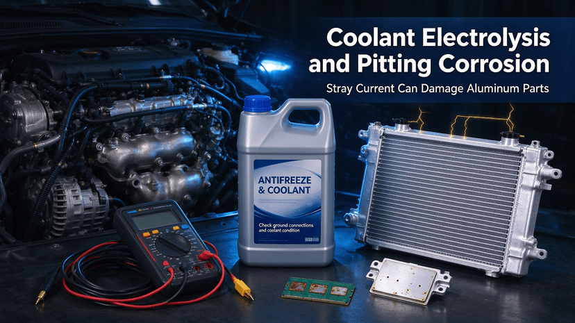
Coolant electrolysis occurs when stray direct current (DC) electricity flows through an engine’s cooling passages seeking ground, turning the liquid coolant into a conductive electrolyte bath. Under normal operating conditions, an engine's electrical system returns current to the battery or chassis ground through dedicated grounding straps, negative battery cables, and direct metal-to-metal contact.
When those paths exhibit high electrical resistance—or fail completely—the current takes the path of least resistance. That path often runs through the engine block, into the coolant, across rubber hoses to the radiator or heater core, and out through structural mounting brackets into the vehicle chassis. As electricity travels through this liquid pathway, it strips electrons away from softer base metals (predominantly aluminum), literally carrying microscopic bits of metal away into the fluid stream.
The primary triggers behind this current diversion include:
- Compromised Ground Straps: Corroded, loose, or severed ground cables between the engine block, frame, and negative battery terminal force starter, alternator, or ignition current through the coolant.
- Faulty Aftermarket Wiring: Improperly grounded auxiliary equipment—such as lift-gate pumps, snowplows, high-draw lighting arrays, or hydraulic coolers—frequently dump return current into the chassis near heat exchangers.
- Alternator Diode Leakage: A malfunctioning alternator with an internal diode failure can push alternating or ripple DC current back through mounting points.
- Coolant Chemistry Breakdown: Over-extended, depleted coolant loses its corrosion inhibitors. As pH drops and mineral salts accumulate, electrical conductivity increases exponentially, worsening the severity of coolant electrolysis.
Electrolysis vs. Galvanic Corrosion: A Crucial Distinction
Engineers often conflate galvanic reaction with active electrolysis, but their root causes and rates of destruction differ substantially.
| Parameter | Galvanic Corrosion | Coolant Electrolysis |
|---|---|---|
| Energy Source | Natural potential difference between dissimilar metals (e.g., cast iron vs. aluminum). | External electrical current (stray DC voltage from vehicle or equipment electrical system). |
| Damage Rate | Slow, steady; often takes years to breach metal walls. | Extremely rapid; can perforate thin aluminum tubes in weeks or days. |
| Primary Driver | Depleted additive packages and mismatched metal nobility. | Missing/damaged ground straps, improper aftermarket wiring, faulty starter/alternator. |
| Voltage Signature | Typically stays below 0.15 volts across the coolant. | Frequently measures between 0.30 and 4.0+ volts during component activation. |
Key Signs of Electrolysis in Cooling System Diagnostics
Identifying the signs of electrolysis in cooling system components requires looking beyond basic thermal performance. Because the destruction is electrochemical, physical indicators appear long before a driver spots a temperature spike.
The most telling visual symptom is localized coolant pitting corrosion, particularly on thin-walled aluminum heat exchangers. Unlike general erosion or chemical scaling, electrolysis creates deep, sharp-edged cratering from the wet side outward. Often, the external face of the radiator tube appears pristine until a microscopic pinhole suddenly vents steam.
Other diagnostic indicators include:
- Rapid Heater Core or Radiator Perforation: Replacing a leaking heat exchanger only to have the replacement fail at the exact same location weeks later.
- Blackened Internal Tubes: Thin, soot-like gray or black deposits coating the interior tube surfaces of aluminum radiators.
- Eroded Pump Impellers: Water pump fins rounded off or pitted, often misdiagnosed as cavitation erosion.
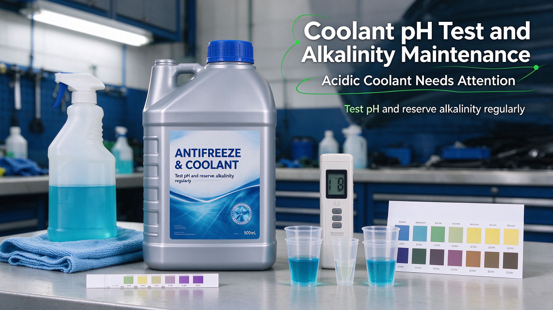
- Discolored or Acidic Coolant: Coolant that rapidly drops in pH (below 7.5 for standard OAT or hybrid formulations) despite recent flushes, carrying suspended gray sludge.
The Real Cost: Antifreeze Electrolysis Damage to Engine Blocks and Heads
While radiators and heater cores take the brunt of the damage due to their thin wall sections, antifreeze electrolysis damage to engine assemblies can be economically fatal for heavy-duty machinery. Wet cylinder liners, aluminum cylinder heads, and timing covers are prime targets.
When stray current targets the interface between an aluminum head and an iron block, the head surface adjacent to the fire ring can corrode rapidly, compromising head gasket sealing. In diesel applications with wet sleeve liners, pitting on the coolant side of the liner wall can erode through the steel sleeve, allowing coolant into the combustion chamber or oil sump. Once engine corrosion reaches structural castings, simple component replacement is off the table; the entire block or cylinder head must be re-machined or scrapped.
Step-by-Step Multimeter Test for Stray Voltage
Pinpointing what causes coolant electrolysis on an active machine takes less than ten minutes with a digital multimeter (DMM). Never rely solely on visual inspection.
- Set your DMM to low-range DC volts (millivolt or 0–20V scale).
- Attach the meter’s negative (-) test lead directly to the negative battery terminal. Ensure the clamp has bare, clean metal contact.
- Submerge the positive (+) probe directly into the coolant via the radiator filler neck or expansion tank. Crucial step: do not allow the probe to touch the radiator filler neck or any internal metal structure. It must touch only liquid.
- Read the static voltage with the engine cold and ignition switched completely off. A healthy system with fresh fluid will typically register between 0.00 and 0.10 volts. Anything between 0.10 and 0.30 volts indicates aging, chemically active fluid nearing its service limit.
- Turn the ignition key to 'Run' without starting the engine. Watch for sudden voltage spikes.
- Start the engine. Turn on every electrical load individually: headlamps, HVAC blowers, auxiliary winches, refrigeration units, and secondary pumps. Have a technician crank the starter while monitoring the display.
If the voltage jumps above 0.30 volts (or routinely exceeds 0.10 volts in sensitive aluminum-intensive powertrains) when a specific accessory activates, you have found the stray current pathway. If the voltage spikes dramatically while cranking, the starter motor's primary ground or block-to-frame grounding strap is deficient.
Prevention and Maintenance Best Practices
Fixing stray current requires addressing both the physical wiring and the chemical health of the fluid. Simply installing a sacrificial zinc anode in the radiator is a temporary band-aid; while it may delay pitting, it does not correct the electrical circuit fault causing the degradation.
Ensure that all structural bonding straps are unpainted, free of oxidation, and secured to bare metal with star washers. When adding aftermarket electronic controls, route return grounds directly to an engineered ground bus or the battery post, rather than tapping into convenient chassis sheet metal or cooling bracketry. Finally, maintain a disciplined coolant testing program: track pH, freeze point, and electrical conductivity at every scheduled service interval to prevent the coolant from turning into an aggressive electrolyte.
Frequently Asked Questions
Can brand-new coolant prevent electrolysis?
New coolant provides robust corrosion inhibitors that slow down damage, but it cannot stop stray DC current. If a major ground strap is severed and current passes through the engine block, even premium factory-fill coolant will quickly lose its inhibitors and allow aluminum pitting.
What voltage level is considered dangerous in a cooling system?
Most commercial powertrain manufacturers consider anything above 0.30 volts DC unacceptable. However, for modern all-aluminum cooling packages, many engineering guidelines set a stricter threshold at 0.10 volts to prevent gradual surface degradation.
Does adding an aftermarket radiator cap with a zinc anode fix the problem?
Anodes attract current and sacrifice themselves first, which can buy brief time, but they do not solve the underlying ground fault. Furthermore, an eroding zinc anode sheds oxidized metal particulates into the cooling system, which can foul narrow radiator passages and heater core tubes.
Welcome to contact GAFLE for more information & cooperation!
peter
ZHEJIANG GAFLE AUTO CHEMICL CO.,LTD
Tel:86-579-8222 1665
Fax:86-579-8246 4690
Cel/Wechart:86-13335993986
E-mail:peter@gafle.net
Web:www.gafle.net